Rafter triangles
Common rafters and the rafter triangles that they define are the starting point for unlocking the secrets of roof construction
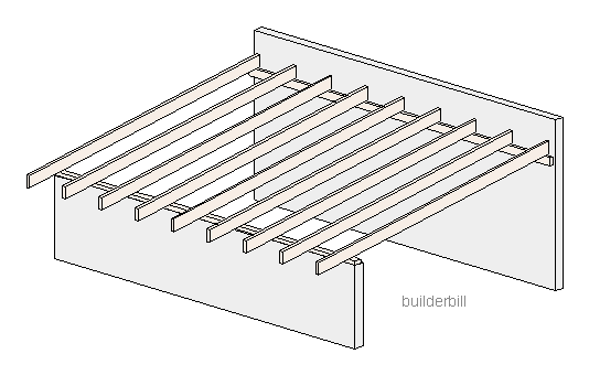 |
| Rafter triangles - 3D sketch of a lean to roof. |
Just about as simple a roof as it is possible to get, the humble shed roof. Sometimes called a lean to roof or here in Australia it also gets called a Skillion roof. It consists of a series of common rafters.
A common rafter runs directly from the ridge to the eaves and it is always fixed at right angles to the ridge.
What you see above is a 3D type of sketch. This type of view is great for a quick illustration to give an instant idea of the general layout.
However it is useless from the point of view of solving roof problems. These views from an angle to the structure do not show us the true lengths or the true angles.
- In roofing we work with Plans, Elevations and Sections.
- A plan is a view of the structure from directly overhead.
- An elevation is a view from a side.
- A section is a view that can be seen if we cut a slice through the structure.
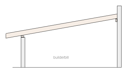 |
| Rafter triangles - A section through the roof parallel to the rafters and square off the walls. |
Above we see the same roof seen in elevation or as a vertical section (or slice) between two of the rafters.
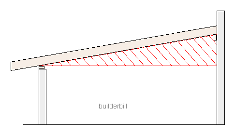 |
| Rafter triangles - The common rafter triangle |
Here I have sketched in a triangle under the rafter.
- I know quite a lot about it at present.
- It has a base which is horizontal because I have drawn it that way.
- It has a side which I have drawn vertical to the base.
- Because one side is vertical and the other horizontal,then I know that the angle between them is 90deg so we have a right angle triangle.
It is easy to see that if we knew all the details of that triangle the we could easily use the information to measure and cut the rafters.
 |
| Rafter triangles - The same triangle as part of a ridged or peaked roof. |
In the sketch above the ridge is in the centre so it is pointless drawing another just the same. The information from one side fits the other as well.
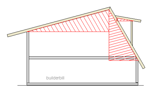 |
| Rafter triangles - Mixed roof pitches in one building |
When the building has different types of roofs and rafters then we just draw a triangle for each and every one.
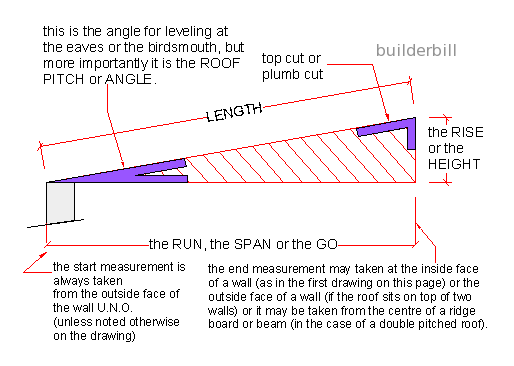 |
| The common rafter triangle in detail |
Above we see again the original triangle and this time I have named the sides.
Solving the triangles. Getting the rest of the information.
This section covers using just drawing to solve the triangles, and once these basics are grasped then it is a fairly simple step to use a cheap pocket calculator to get faster and more accurate results. For using a calculator check out the link to my ebook at the top of the page.
The go is often called the run or the span of the rafter or the roof. It is almost always given on the architectural drawings. The rise or height may be given on the drawings, in which case it is easy to draw in the longest side, measure it and take the bevels or angles. | 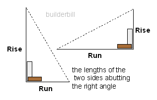 |
More often than not though you will be given the information to get the rise in a different way. At the right is how to get it if only the span and the roof pitch are given.
The base is drawn and a line drawn for the rise. A protractor is used to drawing the angle of the roof and that line is extended to meet the vertical to finish the triangle. | 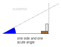 |
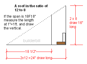
In North America the roof pitch may be given as a ratio, usually with the run as 12 with the rise being the variable.
Draw a triangle at the desired ratio. This will give the pitch or roof slope angles. Then draw the rafter triangle inside or outside that triangle to get the length.
|  |
| Rarely you may have a desired rafter length. Lay out the span and a vertical construction line and then you scribe an arc the length of the desired rafter and where it cuts the vertical is your third point.
The on site substitute for a trammel or a large wing compass to scribe the arc is a length of timber batten with two nails driven through it the desired distance apart. Fine adjustments being done by bending one of the nails. | 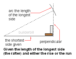 |
Looking again at our original sketch at the top of the page you will see that account has to be taken of the eaves overhang.
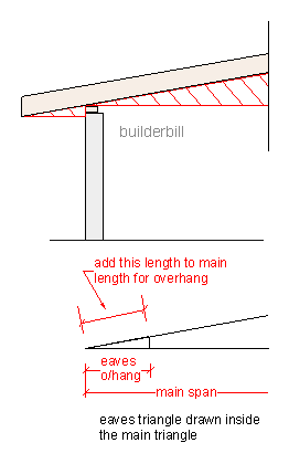
As you can see from the sketch at the right we could simply add the small overhang triangle at the end of the main span. This is OK, but not really good practice. This makes the drawing larger than it needs to be. The whole purpose of drawing roof sections to scale is to do them at a large enough scale so that good level of accuracy can be maintained.
If you add extras like this then our may have to go too a smaller scale to fit it all in and that means less precision in your measurements.
So the answer is to draw the overhang triangle inside the main one. Less work and greater accuracy.
|  |
|
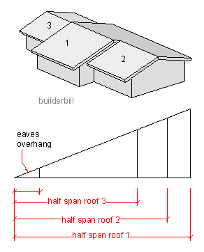
In the previous example we placed one triangle inside another in the interests of keeping the drawing at as large a scale as possible and of course this trick can be used more than once.
The sketch shows a house with three different roof spans.
As long as they are all at the same pitch or roof angle then they can all be combined into the same simple drawing. Just make sure they are all labeled clearly.
|  |


